
A New Method to Improve Performance of Memory Sub-Systems
April 12th, 2016 by Gregg Recupero
Overview
Tomorrow's memory standards hold the promise of higher performance. With the uncertain future of which protocols will emerge as industry standards many system architects conservatively choose from current DDR standards - adopting a "wait and see" approach. However, the needs to improve system performance and reduce power consumption are still paramount with next generation products. With memory subsystems representing significant influences on these two areas, designers must find new methods to improve the performance of memory sub-systems.
Typical performance enhancements, such as increasing clock rates, increasing cache sizes or optimization of software code, all represent design risk or increased power consumption and system cost.
The Performance-IP method discussed here is implemented using small, distributed, logic elements requires no code changes and does not require the increase of system clock rates.
Lost System Performance in Current Architectures
Lost System Performance is design performance that is limited by the current design and/or architecture. To create an example let us assume that read or write operations to today's typical memory sub-system require a minimum of 25 clock cycles (latency) to complete. This minimum value is for light loading of the memory subsystem. As requested traffic increases this latency number will quickly increase. In the case of this example: If the latency for each access to the memory sub-system could be reduced by just 1 clock cycle a savings of millions of cycles would be realized over the execution of the application. The higher the clock rate, the faster the accumulation of savings in time (performance) and system power.
Performance-IP has developed a new technology that dramatically reduces memory sub-system latency thus recovering lost system performance.
Today's Typical System Design
A typical SoC implementation is shown in Figure 1. Faced by design pressures mentioned above, improving power and latency, system architects are asking how performance can be improved with minimal impact on proven architectures and firmware.
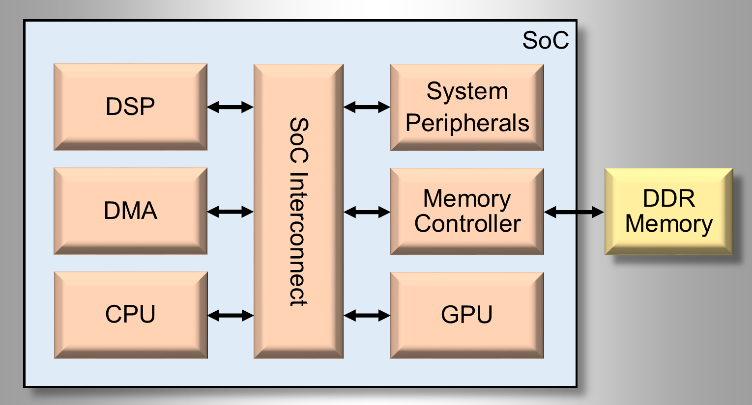
When analyzing areas of possible improvement, designers typically look at each individual system component and assess the effort/risk/reward associated with the improvement or optimization of each of these. Conventional system improvement options typically include increasing current cache sizes, increasing processor clock rate, optimizing the system interconnect or code optimization. A new method, Memory Request Optimization, requires minimal architectural modifications and no code changes to take full advantage of the Performance-IP improvements.
Cache size is typically increased in powers of two. A minimum increase in cache size would require effectively doubling the area of the current cache implementation - affecting both area and power.
Increasing processor clock rate will improve performance and will also directly affect power consumption. Further, if insufficient design head room exists to increase clock rate, additional die area could also be incurred by the addition of hardware to support the increased clock speed. Updating or switching system interconnects could help to reduce the number of clock cycles to the memory sub-system. However, it is unlikely you can reduce this number by half.
The Performance-IP solution addresses the problem at the source by reducing latency at the memory sub-system. By reducing system clock cycles dedicated to memory sub-system latency, direct benefits (power, time) are realized at all levels of the system hierarchy. Data provided later in this paper shows the dramatic improvement provided by this solution across a range of applications.
The Performance-IP Solution - The Memory Request Optimizer
To begin the presentation of the Performance-IP solution we can adapt an old adage to read, "Every clock cycle saved is a clock cycle earned."
Performance-IP's Memory Request Optimizer™ provides a patent-pending latency reduction technology that can revive your DDR sub-system.
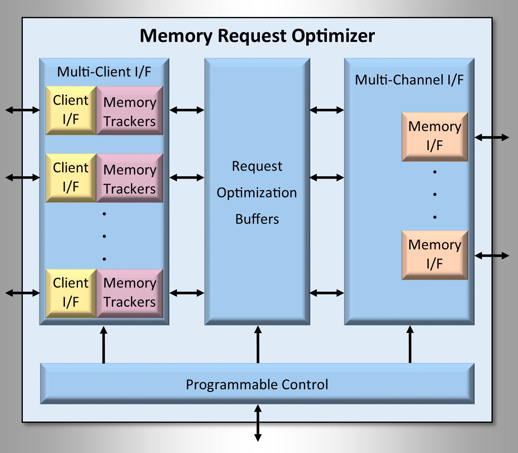
Comprising 5 small logic modules, the Memory Request Optimizer (MRO) fits directly into an existing or new DDR memory hierarchy. Shown in the diagram above are the MRO building blocks, these are:
- Multi-Client Interface
- Memory Trackers
- Request Optimization Buffers
- Multi-Channel Memory Interface
- Programmable Control
Performance-IP MRO Multi-Client Interface
The Performance-IP Multi-Client Interface is capable of supporting 1-16 clients. Designers specify the number of required client's when configuring the MRO. The Performance-IP configuration tool will automatically build the specified number of client interfaces. Each client interface is independent and can support concurrent operation. As a primary benefit: for data contained in the Request Optimization Buffers the ability to handle multiple concurrent client requests allows the MRO to supply a higher peak burst bandwidth than is provided by the underlying memory sub-system. Both AXI and OCP client interfaces are supported on the Multi-Client Interface.
Performance-IP MRO Memory Tracker Technology
The MRO's Memory Trackers implement Performance-IP's patent-pending Memory Tracker Technology™. This technology provides the increased operational efficiency for the Memory Request Optimizer. The Memory Trackers allows different client request streams to be independently tracked and optimized. Each individual Memory Tracker is very small allowing a virtual pool of trackers to be available and allocated on demand. Varying by application, the examples provided in this paper show how system latency is improved as a function of the number of Memory Trackers in use.
Performance-IP MRO Request Optimization Buffers
The Request Optimization Buffers act as a small micro-cache holding optimized client requests. The proprietary algorithm used to fill Request Optimization Buffers utilizes Memory Tracker data profiles. The buffers are far smaller than typical lower level cache memories and offer multiple concurrent system responses by way of the Multi-Client Interface - far outperforming conventional cache subsystems, often at aggregate data rates higher than provided by the system memory subsystem itself, all at lower die area and power.
Performance-IP MRO Multi-Channel Memory Interface
To best support different system design tradeoffs the MRO configuration tool implements a parameterizable multi-Channel Memory Interface. Designers specify the number of memory channels required for their architecture and configure the MRO to instantiate the required number of Memory Interfaces. The Multi-Channel Memory Interface supports both AXI and OCP protocols.
Performance-IP MRO Programmable Control
The MRO Programmable Control provides the ability for the MRO to be dynamically configured for actual system needs. The level of optimization and available Memory Trackers may be assigned dynamically, allowing system performance to be tuned during operation to meet system requirements. The MRO can be programmed to optimize any one or more client request streams. Providing full in system control over the MRO operation.
System Analysis: Performance-IP Memory Request Optimizer
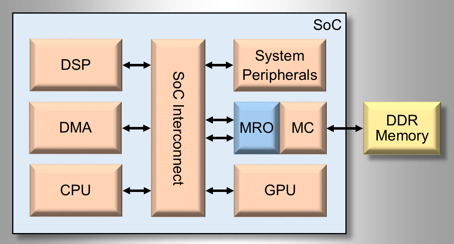
The MRO can be implemented at any point of the memory hierarchy and for any number of clients. For our analysis we implemented a SoC similar to the one shown in Figure 3. Placing the MRO directly in front of the Memory Controller allows all clients to reap in the benefits from the MRO. In our example, at this level of the memory hierarchy requests to external memory required a very conservative 25 clock cycles to complete. Even modeling the subsystem with only 25 cycles of latency the Performance-IP MRO analysis yielded unprecedented results.
Memory Tracker Technology - Case Studies
The key to the Memory Request Optimizer is Performance-IP's patent-pending Memory Tracker Technology. The Memory Trackers are designed to record client request streams. Based on this information and the current mode of optimization, the Memory Trackers determine which requests should be speculatively prefetched. Each Memory Tracker is very small allowing a pool of available Memory Trackers to be enabled and dynamically allocated during operation. To perform the case studies with results shown below four different applications were run. Each application exhibited different workloads and read to write ratios.
The applications run were the following:
- Mesh Generation - Performs finite element analysis using a polygonal or polyhedral mesh.
- Neural Network - Implements a back-propagation neural network.
- Finite Difference - Performs a 2-D stencil computation using finite-difference methods.
- MP3 Decode - Executes MPEG-2 Audio Layer 3 decoder for audio stream.
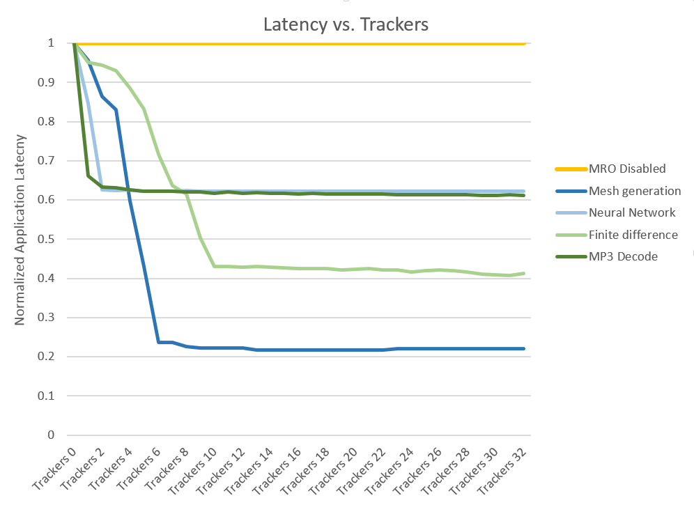
A baseline latency was computed for each application by running with the MRO disabled. Then each application was re-run using each of the MRO optimization modes while successively enabling 1 through 32 Memory Trackers. The column labeled, Cycles of Read Latency in Table 1, represents the total number of clock cycles spent performing read operations for each application across all MRO modes of optimization. The millions of clock cycles saved in read latency can be seen in this column, showing how every clock cycle saved, is a clock cycle of earned performance improvement. This demonstrates the MRO's ability to recover lost system performance that exists in SoC designs.
The average latency was computed across each of the MRO optimization modes for all 4 applications. These results are shown in Figure 4. This analysis shows that once a sufficient number of trackers are operating, the efficiency of the MRO is dramatically improved, reducing latency. This occurs for all applications leveling out once the appropriate number of Memory Trackers are enabled.
Another important improvement was the reduction in reads that reached the external memory system. These reductions actually pay a 2x dividend towards improving system performance. First, any read that occurs on chip consumes 10x less energy than if that same read occurred off chip. The second dividend is the reduction in off-chip memory bandwidth, improving the efficiency of the memory sub-system. The MRO multi-client interface is designed to support multiple concurrent client operations. The operations occurring on-chip, with the MRO, provide a speed-up to the requesting client.
The final metric that was computed was the False Fetch Rate. The False Fetch Rate is the number of requests fetched by the MRO that are never used. These requests must be kept to a minimum because they represent reads that will consume available memory bandwidth. For example, a typical prefetch engine will exhibit false fetch rates of 10-20%. However, the MRO exhibited amazing false fetch rates as low as 0.01% for Low Optimization Mode! Even the worst case number of 2.6% for the Aggressive Optimization modes is much lower than a typical prefetch engine. These dramatically low false fetch rates show the efficiency gained from the Memory Trackers and the improved effectiveness of the Memory Request Optimizer. The application results are shown below in Table 1.
Table 1 - MRO Application Results| Application | MRO Mode | Hit Rate | False Fetch Rate | Cycles of Read Latency | External Memory Reads |
|---|---|---|---|---|---|
| Mesh Generation (14 Trackers) | Disabled | 0% | 0% | 1,428,662 | 49,032 |
| Low | 88% | 0.2% | 449,490 | 48,126 | |
| Moderate | 94% | 1.4% | 373,362 | 47,589 | |
| Aggressive | 97% | 1.6% | 349,020 | 47,458 | |
| Neural Network (10 Trackers) | Disabled | 0% | 0% | 2,541,142 | 86,055 |
| Low | 47% | 0.01% | 1,701,072 | 85,799 | |
| Moderate | 51% | 0.03% | 1,618,083 | 85,884 | |
| Aggressive | 52% | 0.05% | 1,613,058 | 85,853 | |
| Finite Difference (22 Trackers) | Disabled | 0% | 0% | 645,789 | 22,009 |
| Low | 48% | 0.2% | 405,534 | 19,523 | |
| Moderate | 78% | 0.3% | 251,401 | 20,555 | |
| Aggressive | 81% | 0.4% | 238,686 | 19,971 | |
| MP3 Decode (9 Trackers) | Disabled | 0% | 0% | 5,718,771 | 173,234 |
| Low | 40% | 0.2% | 3,832,304 | 154,179 | |
| Moderate | 63% | 0.5% | 2,788,527 | 158,695 | |
| Aggressive | 72% | 2.6% | 2,363,896 | 163,408 |
Solutions from Performance-IP
These reductions in latency will improve the performance of the system components implemented in your SoC, allowing your design to run faster without increasing power consumption. That coupled with the high hit rates allows peak burst bandwidth improvements to requesting clients. These improvements can breathe life back into your DDR Memory sub-system.
Whether your solution is ASIC or FPGA based, everyone can benefit from an improved Memory Sub-System.
For more information on Performance-IPs products please visit our web site at www.Performance-IP.com. Or if you would like to see how much of an improvement the Memory Request Optimizer could provide for system, click this link to Take the Performance-IP Design Challenge.